COMPUTER-GENERATED STEREOGRAMS:A New Dimension For The Graphic Arts
D. Verne Morland
Published in
1. INTRODUCTIONEver since the introduction of stereoscopy in 1838 artists and scientists alike have been intrigued by its extraordinary ability to portray three-dimensional relationships. Except in the case of stereophotography, however, the creation of the requisite left and right two-dimensional perspective images has presented a formidable problem. For many years the binocular parallax, which is the basis of stereopsis, was approximated by separating corresponding points in the left and right images by a distance directly proportional to their depth. In 1966 Chisnell and Winter [1] demonstrated the short-comings of this approach and proposed a computer-based system for synthesizing the true left and right perspective projections of three-dimensional data. Since that time a number of computer driven displays have employed stereoscopic principles to present three-dimensional information; however, the aim of most of these systems has been to communicate technical design structures (automobiles, piping networks) rather than aesthetic constructs. Recently, the fundamental elements of stereoscopy have been integrated with the full color, high resolution, interactive graphics system developed and marketed by General Electric as its GENIGRAPHICS* 100 artwork system. This combination has produced a hybrid two and three-dimensional abstract graphics design tool which affords heretofore unattainable flexibility in the creation of a wide range of art. This paper discusses the genre of graphic images which can be created on this new stereographic system and it considers many of the system design criteria that have an impact on the artistic construction of three-dimensional environments.
2. THE GENIGRAPHICS GRAPHIC DESIGN SYSTEMA rudimentary explanation of the two-dimensional graphic capabilities of the GENIGRAPHICS system must necessarily precede any detailed discussion of a stereoscopic extension. 2. 1 Hardware The basic system is composed of three elements: the Artist's Console, the Graphics Processor, and the High Resolution Recorder. See Fig. 1.
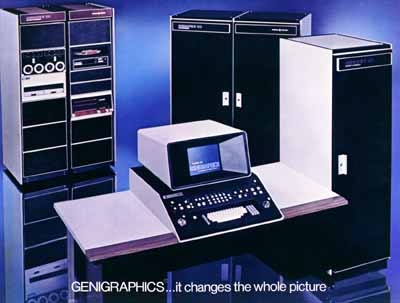 Fig. 1 The Basic GENIGRAPHICS System Configuration The Artist's Console consists of a full-color CRT monitor, solid-state raster display hardware, and a wide variety of input devices an alphanumeric keyboard, two joysticks, five rate knobs, and an array of lighted and unlighted pushbuttons and switches arranged to facilitate the intuitive manipulation of graphic design elements. The Graphics Processor is a 16-bit minicomputer with a 28 kiloword core memory, a high-density, movable head disk for program storage and two magnetic tapes or diskettes for artwork storage. The High Resolution Recorder consists of a 4,000 line monochromatic CRT, a 6-sector color wheel, a 35mm camera, and the camera and image control circuitry. 2. 2 Software In order to provide a versatile foundation for system development and to minimize core memory storage requirements, the GENIGRAPHICS system software is divided into a hierarchical structure of subsystem program modules as shown in Fig. 2.
 Fig. 2 GENIGRAPHICS Software System Structure The software supports the creation and manipulation of five basic graphic entities:
Although the ability to define and control these five classes of graphic elements would be completely satisfactory for most computer-aided design systems intended for the refinement of technical subjects, the interactive capabilities provided by the GENIGRAPHICS system encourage the creation of aesthetic compositions. Typically, objects are not described numerically according to some X-Y reference grid, but rather the basic components of the artwork are interactively defined, positioned, sized, and colored by using the joysticks, rate knobs, and function buttons. The GENIGRAPHICS artist composes his work in real-time with the assistance of rectangular object reference symbols. The actual image is updated only when the artist issues a regeneration command. The artist can use up to 61 different colors in one image and he can choose those colors either from a standard system-defined palette or by specifying hue (0-217), chroma (0-160) and value (O-217) descriptors. The artist can also zoom in on any portion of the image plane for a magnification ranging from 1X to 150X. Furthermore, at the touch of a button the artist can automatically establish a wide variety of design relationships including:
When a piece of artwork has been completed it may be recorded immediately on color positive film or it may be stored in digital form on magnetic tape. Once stored on tape, individual graphic symbols or entire images can easily be recalled and merged into one composite picture.
3. THE STEREOSCOPIC EXTENSIONSince the description of interesting three-dimensional objects and environments is usually both a conceptually difficult and a technically tedious task, the stereoscopic extension of the GENIGRAPHICS system was designed to conform to the following operational criteria:
The first point is the most important for it represents a reaffirmation of the principal axiom of user-oriented system design. Consequently, although the mathematical expressions which describe the fundamental geometry of stereoscopy involve a plethora of independent variables point-of-view coordinates, interocular distance, orientation of the image plane, et cetera the implementation of those equations in the present system reduces the general case to the specific viewing structure illustrated in Fig. 3. Under this system the left and right points-of-view are fixed ((-5x, 0y, l00z) and (+5x, 0y, l00z), respectively), the interocular distance vector is, therefore, (10x, 0y, 0z), and the optic axes, when parallel to each other, are perpendicular to the image plane.
 Fig. 3 Orthostereoscopic Model* of the GENIGRAPHICS Stereospace *Under orthostereoscopic conditions there is no depth distortion. This analysis assumes a standard interocular distance of 62mm. The structure of the GENIGRAPHICS stereospace can best be understood by studying its orthostereoscopic representation (Fig. 3). The artist should imagine that he is sitting in front of a large box (1.5m X 1.5m X 1.lm) with his eyes fixed a short distance (10.2cm) away from the center of the front side. His view into the box is restricted by two viewports which allow both eyes to see through a 46cm X 61cm rectangle on the transparent image plane which is located exactly halfway back in the box. Naturally, with these restrictions he is capable of seeing only those objects which intersect his "cones" of vision. Note that the design of the stereospace prevents the artist from placing any object too close to the viewpoints which would cause convergence-accommodation confusion for the observer and might also tend to obscure a significant portion of the active image area. We satisfy the second criterion by partitioning the depth axis between the front and the back limits with a series of over 47,000 evenly-spaced "depth planes." The artist now considers individual graphic elements to be infinitely thin, opaque shapes that may be suspended in any depth plane. In practice, the artist first constructs the orthographic projection of the three-dimensional environment in the image plane. He then assigns a depth coordinate to each object which implicitly projects it perpendicularly into the appropriate depth plane. Although this convention forces the artist to explicitly correlate the two-dimensional visual priority and the three-dimensional depth assignment (a trivial task for the computer), it was so designed intentionally in order to permit the creation of pseudoscopic image elements. These are objects or groups of objects for which the principal monocular depth cue (interposition) and the binocular depth cue (binocular parallax) are in conflict. Pseudoscopic objects are essential to the creation of transparent and translucent effects. Often the artist may wish to portray a solid object by creating a large number of identical shapes and evenly spacing them very closely together in depth. If this is done properly, the observer will mentally integrate all of the shapes into one cohesive percept. To facilitate the creation of this very powerful illusion as well as other structurally similar constructions (stairs, textures, fence posts), the system provides an automatic linear depth spacing function which requires only the start and stop depth levels and is independent of any X-Y orientation. Finally, to enable the artist to study and to modify the depth relationships within an image interactively, the GENIGRAPHICS stereo system will present both the left and right perspective views on the console monitor simultaneously. When the artist then views the screen through a special prismatic viewing hood (Fig. 4) he will perceive the image in relief*. Should he wish to change the depth coordinate of any object he can easily return to the original, two-dimensional image and modify the depth specification that was in error. *Since the effective image resolution is more than halved by-this split-screen technique, the minimum perceptible depth gradient near the image plane corresponds to roughly 1% of the total depth range.
 Fig. 4 Stereo Viewing Hood 3. 1 Continuous Depth Gradient Problem At this point it may be argued that the existence of single objects which are not parallel to the image plane is essential even to many of the most primitive three-dimensional compositions. If this be the case, which is debatable, it should be noted that it is possible to produce a certain subset of this class of objects, namely, those objects whose depth gradient is piecewise-linear at the boundary. Consider for example, the case of a cube being viewed at an angle from which only the top, the front, and the right side can be seen. If the front is parallel to the image plane, then the two visible sides must necessarily be perpendicular to it. These two surfaces can be precisely created by the following procedure:
 Fig. 5 Stereo Pair Representing the Front and Back Sides of a Cube
 Fig. 6 Top of the Cube
 Fig. 7 Right Side of the Cube The linear, continuous change in parallax that exists along the left and right edges of the top surface and along the top and bottom edges of the right surface is visually consistent with a constant depth gradient. This same concept can be applied to more complex polygons simply by defining the depth value for each vertex. Furthermore, since the interior of each polygon is uniformly colored, it is impossible to visually correlate any two random points in corresponding objects in the left and right images. As a result it is impossible to create a convex or concave contour within a single object. This consequence may be regarded favorably, however, since the absence of any binocular parallax in the interior of any object also precludes the possibility of any parallax-related depth conflicts between the interior and the perimeter. In general, therefore, the depth contour of the interior will be unconsciously interpreted by the brain as that topology that is most consistent (i.e., natural or familiar) with the rest of its graphic environment. The cerebral aspects of depth interpretation are further emphasized by noting the cooperation* between monocular and binocular depth cues. The depth relationships between separate elements of a complex graphic symbol that are suggested by monocular techniques shading, linear perspective, actual size vs. known size relationships, et cetera are significantly enhanced when the entire symbol is projected into a single depth plane by binocular parallax. This appears to be so, despite the conflict between the singular parallax and the multiple depth levels intimated by the monocular clues. Naturally, this sensation is achieved more easily as the perceived distance between the object and the observer increases since the mind is more inclined to ignore more minor, isolated discrepancies in favor of a consistent global structure. This phenomenon is also strongly influenced by the degree of the observer's familiarity with the percept involved. *The use of "cooperation" here is not intended to imply a cooperative system exhibiting disorder-order transitions, hysteresis, and multiple-stable states [2] but rather it is used to describe the simple enhancement or reinforcement of a psychological interpretation by several congruous but independent sensory inputs. 3. 2 Features of Abstract Stereoscopic Images When contemplating how and by whom stereoscopic images might be used it is essential to begin with a review of viewing devices and techniques. Suffice it to say that no one has yet been able to detect any natural dissimilarity between the left and the right visual system which might permit encoding of the left image for acceptance by only the left eye and of the right image for acceptance by only the right eye. Consequently, every viewing scheme must artificially impair the vision of each eye in such a way that the necessary image-eye correlation is achieved. Of the many techniques suggested for this purpose, the most popular have been:
Each of these techniques has its own unique advantages and disadvantages but since they all involve either selective vision impairment or viewing position constraints, prolonged stereo viewing can often become uncomfortable. The stereoscopes (1-3) typically produce the highest quality images but they are usually limited to one viewing position. The parallax barrier, polarized light, and color filter techniques (4-6), all tend to degrade the image quality to some extent but they generally allow the stereo image to be viewed by several people simultaneously. Given an effective viewing strategy, stereograms are usually more interesting than conventional two-dimensional graphics. Some critics might argue that this is primarily due to their novelty alone, yet this explanation is unsatisfactory. In spite of the fact that we receive depth information from a wide variety of monocular or single-image cues, nevertheless, we will never confound a flat picture with its subject. In contrast to this, Wheatstone noted in 1838 that "careful attention would enable an artist to draw and paint the two component pictures [of a stereogram], so as to present to the mind of the observer, in the resultant perception, perfect identity with the object represented." [5] This hypothesis has been substantiated by modern stereophotographs which engender visual sensations that are virtually indistinguishable from those produced directly by the subject environments. When portraying abstract three-dimensional scenes, binocular parallax becomes even more important due to the absence of many monocular cues. Within the artificial world of the GENIGRAPHICS stereospace the observer cannot rely on many of the usual depth cues which typically facilitate depth localization in real space. Despite the absence of these visual prompts, the depth relationships in a GENIGRAPHICS stereoslide are so startling that the composition seems almost tangible. The obvious conclusion to be drawn from this experience is that a well-designed stereo presentation is capable of maintaining a higher level of audience interest than a two-dimensional presentation even though the semantic information may be the same (cf. black-and-white vs. color presentations). The second important advantage which stereoscopy holds over single-image information display is that the depth sensation that is communicated by binocular parallax appears to be more basic and straightforward than that implied by monocular cues. As Julesz, observes: "Most of the monocular depth cues require a tremendous memory capacity; for instance, familiarity with perceived objects implies a [mental] catalog of no mean extent. Since stereopsis is a more elementary perceptual process, this means that it is applicable to the problem of conveying three-dimensional constructions to individuals who may lack familiarity with many of the complex rules for perspective projection. For example, a six year old child may be unprepared to interpret the three-dimensional significance of Fig. 8 and yet clearly understand the stereoscopic cube that resulted from the construction process outlined in Fig. 5, 6, 7. Stereoscopy, therefore, is an ideal technique for conveniently communicating a very strong sense of three-dimensional relationships without relying on any graphics experience.
 Fig. 8 Cube One-Point Perspective Furthermore, even those individuals who are skilled in interpreting planar views of three-dimensional objects find that stereoscopy tends to improve their ability to envision complex structures by a "qualitative order of magnitude." To illustrate this point, consider the fact that many experienced chemists who have dealt with planar projections of molecular structures for most of their lives now rely heavily on stereoscopic representations of the more complex organic compounds in order to gain a detailed understanding of their structure. Thus, the dimensional clarity of stereograms has great appeal to novice and expert alike.
4. CONCLUSIONStereoscopy is not a new idea. Over the years, thousands of artists, scientists, and engineers have sought to simplify both the stereogram creation and the viewing problems to the end that this remarkable capacity for three-dimensional communication might become a practical reality. The stereographic system presented here succeeds in simplifying the creation of stereograms which portray abstract aesthetic compositions. This is not an analysis tool for the research scientist or engineer; rather it is an instrument through which the artist can experiment with an exciting new medium for sculptural expression. With this new freedom some new responsibilities and disciplines are imposed. Just as the creation of any preconceived composition has always demanded a systematic approach to both the subject and the medium; so, too, the creation of a truly imaginative environment within the GENIGRAPHICS stereospace requires careful planning and the talented manipulation of this sophisticated tool.
ACKNOWLEDGEMENTSThis work was inspired by the exciting research on stereopsis and optical pattern recognition conducted by Dr. Bela Julesz of Bell Laboratories. Through the invention and application of his random-dot stereograms, Dr. Julesz has significantly advanced our understanding of the fascinating realm of Cyclopean perception. Special thanks go also to my colleagues at the General Electric Company for the design, manufacture, and maintenance of the GENIGRAPHICS 100 computerized art system on which this stereographic system was founded.
APPENDIX
REFERENCES
[2]Bela Julesz, Cooperative phenomena in binocular depth perception, American Scientist, vol. 62, January-February, 1974, 3 2-43. [3]Sam H. Kaplan, Theory of parallax barriers, Journal of the SMPTE, vol. 59, July, 1952, 11. [4]Andrew Ortony, The transmission reflection method for stereo viewing, The Computer Journal, 1970, 140-144. [5]Charles Wheatstone, On some remarkable, and hitherto unobserved, phenomena of binocular vision, Roy Soc London Phil Trans, 1838, 376. [6]Bela Julesz, Binocular depth perception of computer-generated patterns, Bell System Technical Journal, vol. 39, no. 5, September, 1960, 1131. |
||||||||||||||